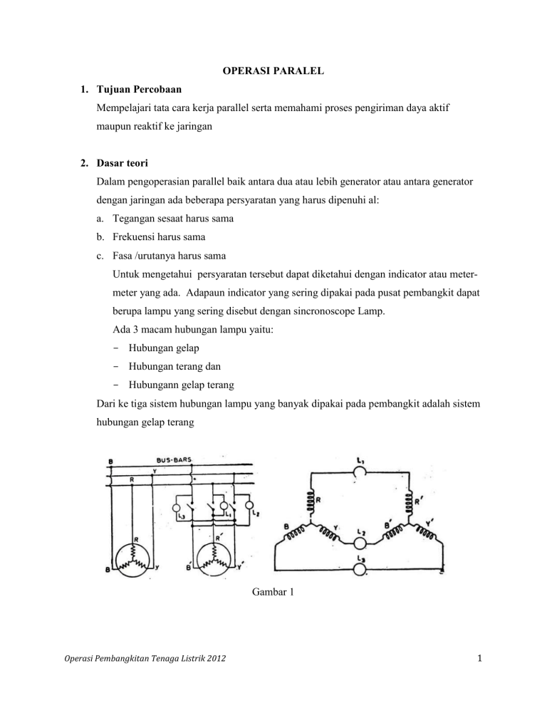
OPERASI PARALEL 1. Tujuan Percobaan Mempelajari tata cara kerja parallel serta memahami proses pengiriman daya aktif maupun reaktif ke jaringan 2. Dasar teori Dalam pengoperasian parallel baik antara dua atau lebih generator atau antara generator dengan jaringan ada beberapa persyaratan yang harus dipenuhi al: a. Tegangan sesaat harus sama b. Frekuensi harus sama c. Fasa /urutanya harus sama Untuk mengetahui persyaratan tersebut dapat diketahui dengan indicator atau metermeter yang ada. Adapaun indicator yang sering dipakai pada pusat pembangkit dapat berupa lampu yang sering disebut dengan sincronoscope Lamp. Ada 3 macam hubungan lampu yaitu: - Hubungan gelap - Hubungan terang dan - Hubungann gelap terang Dari ke tiga sistem hubungan lampu yang banyak dipakai pada pembangkit adalah sistem hubungan gelap terang Gambar 1 Operasi Pembangkitan Tenaga Listrik 2012 1 Gambar 2 Gambar 3 Besarnya daya yg dapat ditransfer dari generator 1 ke generator 2 adalah 𝐸1 𝐼𝑠𝑦 cos 𝛷1 = 𝐸1 𝐼𝑠𝑦 (𝛷1 𝑛𝑖𝑙𝑎𝑖𝑛𝑦𝑎 𝑘𝑒𝑐𝑖𝑙) Pada saat sinkron tegangan generator 1 da generator 2 adalah sama maka 𝐸1 = 𝐸2 = 𝐸 Daya yang diterima generator 2 adalah 𝐸2 𝐼𝑠𝑦 cos 𝛷2 = 𝐸2 𝐼𝑠𝑦 𝐸1 𝐼𝑠𝑦 = 𝐸2 𝐼𝑠𝑦 + 𝐶𝑢 𝑙𝑜𝑠𝑠𝑒𝑠 Operasi Pembangkitan Tenaga Listrik 2012 2 𝐸1 = 𝐸2 = 𝐸 𝐸𝑟 = 2𝐸𝑐𝑜𝑠(1800 −∝)/2) ) 𝐸𝑟 = 2𝐸𝑠𝑖𝑛 ∝/2 𝐸𝑟 = 2𝐸 𝑋 ∝/2 𝐸𝑟 =∝ 𝐸 Gambar 4 menunjukkan pengirimman data reaktif sedankan gambar 5 mennjukkan pengiriman daya aktifdaya Gambar 4 Gambar 5 Operasi Pembangkitan Tenaga Listrik 2012 3 3. Rangkaian percobaan U W L1 V V V A L2 W W L3 V Gambar 4 Operasi Pembangkitan Tenaga Listrik 2012 4 4. Langkah percobaan a. Buat rangkaian seperti pada gambar berikut b. Jalankan motor generator dan atur putaran motor hingga 3000 rpm c. Jalankan arus eksitasi generator dan atur hingga tegangan keluaran generator sama dengan tegangan jaringan d. Amati sincronous cope lamp dan perhatikan pula penunjukan volt meternya e. Atur putaran motor sedemikian rupa sehingga frekuensi generator sama dengan frekuensi jaringan f. Dengan seksama perhatikan defleksi jarum pada volt meter dan pada saat defleksi jarum pada simpangan terkecil masukkan saklar untuk sinkron. g. Setelah sinkron lakukan pengiriman daya aktif dengan cara mengatur putaran motornya h. Catat meter-meternya i. Ulangi langkah g untuk melakukan pengiriman daya reaktif dengan cara menambah arus eksitasi pada generatornya j. Buatlah diagram kurva capability nya Operasi Pembangkitan Tenaga Listrik 2012 5 Capability Curve of a Synchronous Generator The Capability Curve of a Synchronous Generator defines a boundary within which the machine can operate safely. It is also known as Operating Charts or Capability Charts. The permissible region of operation is restricted to the following points given below. The MVA loading should not exceed the generator rating. This limit is determined by the armature of the stator heating by the armature current. The MW loading should not exceed the rating of the prime mover. The field current should not be allowed to exceed a specified value determined by the heating of the field. For steady state or stable operation, the load angle δ must be less than 90 degrees. The theoretical stability limit of the stable condition occurs when δ = 90⁰. The capability curve is based upon the phasor diagram of the synchronous machine. The phasor diagram of a cylindrical rotor alternator at lagging power factor is shown below. For simplicity, the armature resistance and saturation are assumed to be negligible. The machine is assumed to be connected to constant voltage Busbars so that the voltage Vp is constant. The length O’O (= Vp) is fixed. The axes Ox and Oy are drawn with its origin O at the tip of Vp. Operasi Pembangkitan Tenaga Listrik 2012 6 From the phasor diagram, The real power output of the generator is given as The reactive power output of the generator is given as A typical capability curve for a cylindrical rotor generator is shown below. Operasi Pembangkitan Tenaga Listrik 2012 7 The curve is plotted on the S-plane, where P is the vertical axis and Q is the horizontal axis. For constant power Ia and volt-amperes S = VA, the locus is a circle with center at O and radius OB (= 3 Vp Ia). Constant P operation lies on a line parallel to Q axis. The constant excitation locus is a circle with center O’ and radius O’B ( = 3 Vp Ef/Xs). Constant power factor lines are straight radial lines from O. For excitation Ef equal to zero, the armature current is given as = short circuit current at rated voltage Operasi Pembangkitan Tenaga Listrik 2012 8 = OO’ The theoretical stability limit is a straight line O’M at right angles to O’O at O’. Here δ = 90⁰. Between a and b, the operation of the alternator is limited by the maximum field current, and a circle of radius (3 V Ef/ Xs) with center O’. Between b and c, the operation is limited by the MVA limit. Here Ia is the maximum permissible armature current. Between c and d, the operation is limited by the power of the prime mover. Between d and e, the operation is limited by the practical stability limit. The theoretical limit of stability occurs where δ = 90⁰. But there must be a safety margin between the theoretical limit and that used in practice. The practical limit is usually taken 10% less than the theoretical stability limit. The complete operating zone of the alternator is abcdkOa. The operation of the alternator within this area is safe from the standpoints of heating and stability. Once an operating point is located within this area, the desired power P, S, Q Current, power factor and excitation are found. Consider the figure given below. Here an operating point F is considered, and the following information is given If the point F is inside the capability curve, the machine will not be overheated and will not be likely to fall out of synchronism. Operasi Pembangkitan Tenaga Listrik 2012 9 A line from F to the origin O’ of the If is at an angle δ from the axis. A line FG through F parallel to O’Oa give power equal to OG. A line from F to the origin O of the Q axis gives the power factor angle ϕ from the vertical axis. i.e., ∠FOG = ϕ The armature current Ia is given by OF. The VA output is given by (OF x operating voltage) The VAr output is given by GF x output voltage O’F gives the excitation Ef. Related terms: 1. 2. 3. 4. 5. V Curve of a Synchronous Motor Power-Angle Curve Short Circuit Ratio of a Synchronous Machine Armature Reaction in a DC Generator Voltage Regulation of a Synchronous Generator Read more: http://circuitglobe.com/capability-curve-of-a-synchronousgenerator.html#ixzz4r5jqSeu0 Operasi Pembangkitan Tenaga Listrik 2012 10
