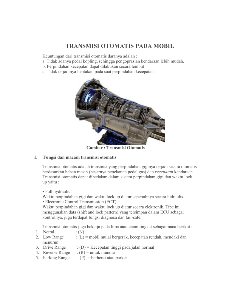
TRANSMISI OTOMATIS PADA MOBIL Keuntungan dari transmisi otomatis daranya adalah : a. Tidak adanya pedal kopling, sehingga pengoprasian kendaraan lebih mudah. b. Perpindahan kecepatan dapat dilakukan secara lembut c. Tidak terjadinya hentakan pada saat perpindahan kecepatan Gambar : Transmisi Otomatis 1. Fungsi dan macam transmisi otomatis Transmisi otomatis adalah transmisi yang perpindahan giginya terjadi secara otomatis berdasarkan beban mesin (besarnya penekanan pedal gas) dan kecepatan kendaraan. Transmisi otomatis dapat dibedakan dalam sistem perpindahan gigi dan waktu lock up yaitu : • Full hydraulic Waktu perpindahan gigi dan waktu lock up diatur sepenuhnya secara hidraulis. • Electronic Control Transmission (ECT) Waktu perpindahan gigi dan waktu lock up diatur secara elektronik. Tipe ini menggunakan data (shift and lock pattern) yang tersimpan dalam ECU sebagai kontrolnya, juga terdapat fungsi diagnosa dan fail-safe. 1. 2. 3. 4. 5. Transmisi otomatis juga bekerja pada lima atau enam tingkat sebagaimana berikut : Netral : (N) Low Range : (L) = mobil mulai bergerak, kecepatan rendah, mendaki dan menurun Drive Range : (D) = Kecepatan tinggi pada jalan normal Reverse Range : (R) = untuk mundur Parking Range : (P) = berhenti atau parker 6. Angka 2 : digunakan untuk menurun Perubahan kecepatan pada transmisi otomatis bergantung kepada injakan pedal gas dan kecepatan poros kopel(profeller shaft). Dengan demikian jika tuas pengatur terpasang pada posisi Low range, kendaraan akan mulai berjalan dari low gear dan secara otomatis berpindak ke hight gear (kecepatan tinggi). Kemudian apabila diperlukan momen yang besar, dengan menekan pedal akselerasi transmisi akan segera berpindah dari hight gear ke low gear. Perpindahan secara otomatis ini dapat dicapai sampai kecepatan 60 Km/jam. Diatas kecepatan 60 tidak akan terjadi pemindahan walaupun pedal akselerasi ditekan dalam-dalam. Hal tersebut dimaksudkan agar pada mesin tidak terjadi kecepatan putar yang berlebihan. 1. 2. a. b. c. Automatic Transmission terdiri dari : Full hydraulic ECT meliputi : Pengaturan shift dan lock up timing Fungsi Diagnosa Fungsi fail-safe d. Lain-lain Gambar : Macam-macam transmisi 2. KEUNTUNGAN TRANSMISI OTOMATIS (FULL HYDRAULIC) Dibandingkan dengan transmisi manual, transmisi otomatis mempunyai beberapa keuntungan sebagai berikut: • Mengurangi kelelahan pengemudi karena tidak ada pengoperasian pedal kopling dan pemindahan gigi. • Perpindahan gigi terjadi secara otomatis dan lembut. • Mengurangi beban mesin karena mesin dan pemindah daya dihubungkan melalui fluida secara hidraulis (torque converter). 3. KEUNTUNGAN ECT Dibandingkan dengan transmisi otomatis full hydraulic, ECT mempunyai beberapa keuntungan sebagai berikut: • Pengemudi dapat memilih mode penggendaraan. • Mengurangi getaran perpindahan gigi • Pemakaian bahan bakar lebih irit • Mempunyai fungsi diagnosa dan memori • Mempunyai fungsi fail safe Gambar : Konstruksi transmisi otomatis 4. JENIS-JENIS TRANSMISI OTOMATIS Transmisi otomatis dapat dibagi menjadi dua jenis, yaitu: • Automatic transaxle, digunakan untuk kendaraan FF (Front-engine, Front-wheeldrive). • Automatic transmission, digunakan untuk kendaraan FR (Front-engine, Rear-wheeldrive) Gambar : Jenis-jenis Transmisi 5. KOMPONEN-KOMPONEN UTAMA Transmisi otomatis terdiri dari beberapa komponen utama sebagai berikut: • Torque converter • Planetary gear unit • Hydraulic control unit • Manual linkage • Automatic transmission fluid 6. TORQUE CONVERTER Torque converter dan kopling fuida mempunyai konstruksi dan prinsip kerja yang sama. Seperti halnya pada kopling fluida, torque converter dipasang pada sisi input shaft transmisi dan diikat dengan baut terhadap bagian belakang poros engkol mesin melaluidrive plate. Sedikit perbedaan dengan kopling fluida, torque converter dilengkapi dengan sudu-suduyangberbentuk kurva dan dilengkapi dengan sebuah stator yang dipasangkan diantara pump impeller dan turbine runner. Pada torque converter, stator merubah aliran minyak ini sama dengan arah putaran pompa impeller dan ini tidak memungkinkan merubah momen dengan menggunakan tenaga yang tertinggal di dalam minyak. Bila terdapat perbedaan putaran yang besar antara pompa impeller dan turbine runner, seperti halnya pada waktu mesin hidup dan propeller shaft masih dalam keadaan berhenti maka aliran minyak diantara kedua bagian menjadi lebih kuat dan stator akan segera menyesuaikan diri untuk emncapai momen yang besar. Pada saat kecepatan turbine mendekati kecepatan pompa, putaran minyak akan mengalir berangsur-angsur berkurang sampai mencapai perbandingan 1 : 1, maka titik. Torque converter merubah momen dalam langkah yang tidak terbatas. Pada putaran idling atau dalam keadaan di rem, di dalam coverter tetap terjadi sirkulasi minyak, tetapi tidak memberikan penambahan momen (tergelincir atau slip) dan berfungsi sebagai kopling seperti halnya kopling fluida. Fungsi torque converter adalah: • Memperbesar momen • Sebagai kopling otomatis • Meredam getaran perpindahan daya • Sebagai flywheel • Mengerakkan pompa oli Komponen utama : 1. Torque converter 2. Transmission case 3. Transmission input shaft 4. Drive plate Gambar : Komponen-komponen torque converter Keterangan : 1. Stator shaft 2. Stator 3. Pump Impeller 4. Turbine Runner 5. Converter case 6. Oil pump 7. Transmission input shaft 8. One – Way Clutch 6.1. Prinsip Kerja : 6.1.1. Kendaraan berhenti , mesin idling Pada saat mesin idle moment yang dihasilkan oleh mesin adalah minimum . Bila rem dioperasikan ( parking / foot brake ) beban pada turbine runner menjadi besar karena tidak dapat berputar . Akibat kendaraan berhenti, maka perbandingan kecepatan antara pompa impeller dan turbine runner nol sedangkan torque rationya maksimum . Oleh karena itu, turbine runner akan selalu siap untuk berputar dengan moment yang dihasilkan oleh mesin. Gambar : Prinsip kerja Torque converter 6.1.2. Kendaraan mulai bergerak Pada saat rem dibebaskan, maka turbine runner dapat berputar dengan poros input transmisi. Dengan menekan pedal Akselerator, maka turbine runner akan berputar dengan moment yang lebih besar dari yang dihasilkan oleh mesin, jadi kendaraan mulai bergerak. 6.1.3. Kendaraan berjalan dengan kecepatan rendah. Bila kecepatan kendaraan bertambah, putaran turbine runner dengan cepat mendekati pompa impeller. Torque rationya dengan cepat mendekati 1,0. Pada saat perbandingan putaran turbine runner dan pompa impeller mendekati angka tertentu ( Clutch Point ) , stator mulai berputar . Dengan kata lain Torque Converter mulai bekerja sebagai kopling fluida. Oleh karena itu kecepatan kendaraan naik hampir berbanding lurus dengan putaran mesin. 6.2. KONSTRUKSI 6.2.1. PUMP IMPELLER Pump impeller disatukan dengan converter case dan converter case dihubungkan ke poros engkol melalui drive plate, ini berarti pump impeller akan berputar saat poros engkol berputar. Pump impeler berfungsi untuk melemparkan fluida (ATF) ke turbine runner agar turbine runner ikut berputar. Pump impeller terdiri dari vane dan guide ring. Guide ring berfungsi untuk membentuk celah yang memperlancar aliran minyak. 6.2.2. TURBINE RUNNER Turbine runner dihubungkan dengan over drive input shaft transmisi, ini berarti turbine runner berfungsi untuk menerima lemparan fluida dari pump impeller dan memutarkanover drive input shaft transmisi. Turbine runner terdiri dari vane dan guide ring. Arah vane pada turbine runner berlawanan dengan vane pump impeler 6.2.3. STATOR Stator ditempatkan di tengah-tengah antara pump impeller dan turbine runner. Dipasang pada poros stator yang diikatkan pada transmission case melalui one way clutch. Stator berfungsi mengarahkan fluida dari turbine runner agar menabrak bagian belakang vane pump impeller, sehingga memberikan tambahan tenaga pada pump impeller. One way clutch memungkinkan stator hanya berputar searah dengan poros engkol. Oleh karena itu, stator akan berputar atau terkunci tergantung dari arah dorongan minyak pada vane stator. Gambar : Konstruksi Pump Impeller, Turbine Runner dan Stator 6.3. CARA KERJA ONE WAY CLUTCH 6.3.1. Outer Race Berputar Searah Putaran Poros Engkol Saat outer race berputar searah putaran poros engkol, ia akan mendorong bagian atas sprag. Karena panjang l1 lebih pendek dari l , maka outer race berputar 6.3.2. Outer Race Berputar Berlawanan Arah Putaran Poros Engkol Bila outer race berputar berlawanan arah putaran poros engkol, sprag tidak dapat miring karena panjang l2 lebih panjang dari l. Akibatnya sprag berfungsi sebagai baji yang mengunci outer race dan mencegahnya berputar. Retainer spring dipasang untuk menjaga posisi sprag sedikit menghadap ke atas pada arah hampir mengunci outer race. 6.4. PRINSIP PEMINDAHAN TENAGA Bila kita memasang dua buah kipas angin A dan B berhadapan satu sama lain, kemudian kipas angin A dihidupkan, maka kipas angin B akan ikut berputar dengan arah yang sama. Ini terjadi karena aliran udara dari kipas angin A membentur daun (vane) kipas angin B dan selanjutnya kipas angin B akan terbawa berputar. Dengan kata lain, terjadi pemindahan tenaga dari kipas angin A ke kipas angin B melalui angin sebagaiperantara. Torque converter bekerja dengan cara yang sama, pompa impeller memainkan peranan kipas A dan turbine runner sebagai kipas B. perantaranya adalah fluida (ATF). Dalam keadaan yang sama, pompa impeller diputarkan oleh mesin yang memberikan energy dinamik pada minyak. Karena gaya centrifugal minyak dengan energy dinamik mengalir sepanjang permukaan kurva pompa impeller dan keluar dari bagian tengah kebagian luar dengan kecepatan yang tinggi, dan dengan sudut yang tertentu mendorong kipas-kipas turbine runner untuk memberikan momen . Momen ini adalah tenaga yang memutarkan turbin sama dengan pompa impeller dan memungkinkan keduanya berputar dalam satu kesatuan. Ini adalah cara kerja kopling fluida. Gambar : Prinsip PemindahanTenaga 6.5. PRINSIP PEMBESARAN MOMEN Pada kedua kipas yang diceritakan sebelumnya ditambahkan air duct, udara yang mengalir ke kipas B akan dikembalikan ke kipas A dari belakang melaui air duct. Ini akan menyebabkan energi yang tertinggal di udara setelah melalui kipas B akan membantu putaran kipas A. Dalam torque converter, stator berfungsi sebagai air duct Gambar : Prinsip Pembesaran Momen 7. Mekanisme Lock Up Clutch (sistem ECT) Pada coupling range ( tidak ada peningkatan momen puntir ) Torque Converter meneruskan momen input dari mesin ke transmisi pada ratio mendekati 1 : 1. Pada pompa Impeller dan Turbine Runner paling sedikit terdapat perbedaan kecepatan putar 4 sampai 5 %. Oleh sebab itu , Torque Converter tidak memindahkan 100 % tenaga yang dibangkitkan oleh mesin ke transmisi, jadi terdapat kerugian energi. Untuk mencegahnya dan untuk mengurangi penggunaan bahan bakar, lock up clutch secara mekanik menghubungkan pompa Impeller dengan Turbine Runner pada saat kecepatan kendaraan mencapai 60 km/jam atau lebih , dengan demikian hampir 100 % tenaga yang dibangkitkan oleh mesin diteruskan ke transmisi. Cara kerja Lock Up Clutch bekerja berdasarkan aliran fluida yang mengalir ke Torque Converter. Saat kendaraan berjalan lambat, Converter Pressure mengalir ke bagian depan Lock Up sehingga Lock Up tidak bekerja . Engine--- Drive Plate ---Front Cover Pump Impeller --- Turbine Runner ---Turbine Runner Hub--- Input Shaft Gambar : Cara Kerja Lock Up Clutch Kecepatan sedang/tinggi Saat kendaraan kecepatan sedang s/d tinggi . Aliran fluida menekan Lock – Up ke arah Converter Case sehingga Lock – Up Clutch bekerja. Engine ---Drive Plate --Front Cover ( Converter Case ) ---Lock Up Clutch ---Turbine Runner Hub--- Input Shaft. Gambar : Cara Kerja Lock Up Clutch Kecepatan sedang/tinggi 8. PLANETARI GEAR UNIT 8.1. Fungsi : 1. Merubah perbandingan gigi, untuk merubah momen dan kecepatan 2. Memungkinkan gerakan mundur 3. Memungkinkan gigi mundur Planetari Gear set mempunyai tiga macam gigi yaitu : 1. Ring gear 2. Sun gear 3. Pinion gear. Pinion gear dipasang pada Carrier . Pinion gear berhubungan dengan Sun gear dan Ring gear. Gambar : System Planetary Gear 8.2. Cara kerja : Sun gear, Ring gear maupun pinion Gear ( carrier ) terkunci dengan gigi lain yang beraksi sebagai input dan output sehingga terjadi percepatan, perlambatan dan gerakan mundur. 8.2.1. Perlambatan Cara kerja roda gigi Ring gear - Drive member (penggerak) = input Sun gear - Fixed (ditahan) Carrier –Driven member ( digerakkan ) = output Bila Ring gear berputar searah jarum jam, pinion gear akan berputar mengelilingi Sun gear sambil berputarsearah jarum jam. Ini menyebabkan putaran Carrier menjadi lambat sesuai dengan banyaknya gigi Ring gear dan Sun gear. 8.2.2. Percepatan Cara kerja roda gigi Ring gear--- Driven member (digerakkan) = output Sun gear --Fixed ( ditahan ) Carrier --- Drive member ( penggerak ) = input. Bila Carrier berputar searah jarum jam, pinion gear akan berputar mengelilingi Sun gearsambil berputar searah jarum jam. Ini menyebabkan putaran Ring gear menjadi cepat sesuai dengan jumlah gigi Ring gear dan sun gear, Dan ini berlawanan dengan contoh di atas. 8.2.3. Mundur Cara kerja roda gigi Ring gear - Driven member ( digerakkan ) Sun gear - Drive member ( penggerak ) Carrier - Fixed ( ditahan ) Bila sun gear berputar searah jarum jam, pinion gearyang terikat pada carrier akan berputar berlawanan dengan jarum jam dan mengakibatkan Ring gear juga berputar berlawanan dengan jarum jam. Pada saat ini Ring gear menjadi lambat sesuai dengan jumlah gigi Sun geardan ring gear. 9. GEAR RATIO Jumlah gigi digerakkan Gear Ratio = -----------------------------Jumlah gigi pernggerak Karena Pinion gear bekerja sebagai idle gear , jumlah giginya tidak dikaitkan dengan gear ratio. Oleh karena itu , gear ratio Planetary gear ditentukan oleh jumlah gigi carrier, ring gear dan sun gear. Karena carrier bukan merupakan gigi, banyaknya gigi perumpamaan dipergunakan pada carrier. Banyaknya gigi carrier Zc dapat diperoleh dengan persamaan : Zc = Zr + Zs Di mana , Zc = jumlah gigi carrier Zr = jumlah gigi ring gear Zs = jumlah gigi sun gear Contoh : Zr = 56 dan Zs = 24 , jika Sun gear fixed ( mati) dan Ring gear bekerja sebagai penggerak, maka gear ratio dari Planetary gear set adalah sbb : Digerakkan GR = -----------------Menggerakkan = Zr + Zs Zr = 56 + 24 5 = 1,429 Jumlah gigi Carrier = ----------------------Jumlah gigi Ring gear 10. Planetary gear unit 3 kecepatan • Counter drive gear diikatkan oleh alur dengan intermediate shaft dan berkaitan dengan counter driven gear. • Front dan rear sun gear berputar bersama sebagai satu unit • Front planetary carrier dan rear planetary ring gear masing-masing diikatkan oleh alur dengan intermediate shaft. 11. FUNGSI MASING – MASING ELEMEN NAMA Forward Clutch (C1) Direct Clutch (C2) gear 2nd FUNGSI Menghubungkan input shaft dengan front ring gear Menghubungkan input shaft dengan front danrear sun Coast Mengunci front dan rear sun gear.mencegahberputarnya searah jarumjam maupun berlawanan jarum jam. Brake (B1) 2nd Brake (B2 ) 1 st Reverse Brake (B2) Mengunci front dan rear sun gear, supaya tidak berputar berlawanan dengan jarum jam, pada saat F, kerja. Mengunci planetary carrier supaya tidak berputar searah maupun berlawanan dengan jarum jam. One-way Clutch No. 1 (F1) Pada saat B2 bekerja, mengunci front dan rear sun gear supaya tidak berputar berlawanan dengan jarum jam. One-way Cutch No. 2 (F2) Mengunci planetary carrier supaya tidak berputar berlawanan dengan jarum jam. 12. SISTEM KONTROL HIDROLIK Hydraulic control system merubah beban mesin (sudut pembukaan throttle valve) dan kecepatan kendaraan menjadi bermacam-macam tekanan hidrolik yang akan menentukan shifting. Sistem ini terdiri dari oil pump, governor valve, dan valve body. Oil pump drive gear berhubungan dengan pump impeller pada torque converter dan selalu berputar dengan kecepatan yang sama dengan kecepatan mesin. Governor valve digerakkan oleh drive pinion dan mengubah putaran (kecepatan) drive pinion shaft menjadi hydraulic signal yang dikirimkan ke valve body. Valve body menyerupai jalan yang berliku-liku, mempunyai jalur-jalur yang banyak sebagai saluran minyak transmisi. Pada jalurjalur ini dipasang banyak katup yang membuka dan menutup jalur-jalur ini untuk mengirimkan dan menghentikan “hydraulic signal”ke bagian-bagian planetary gear unit. OIL PUMP Oil pump dirancang untuk mengirimkan minyak ke torque converter, melumasi planetary gear unit dan mengoperasikan tekanan kerja pada hydraulic control system. Drive gear dari oil pump terus menerus digerakkan oleh mesin melalui torque converter pump impeller. TEKANAN MINYAK Line pressure fungsinya : Diatur oleh primary regulator valve, ini adalah tekanan yang paling dasar dan terpenting yang digunakan pada transmisi otomatis, karena berfungsi untuk mengoperasikan semua kopling dan brake dalam transmisi, dan juga karena ini adalah sumber semua tekanan yang lain (governor pressure, throttle pressure dll) yang digunakan pada transmisi otomatis. Converter pressure dan lubrication pressure fungsinya : Dihasilkan oleh secondary regulator valve, ini digunakan untuk mengalirkan minyak ke torque converter, melumasi transmission case dan bearing dll serta untuk mengirimkan minyak ke oil cooler Throttle pressure fungsinya : Throttle prssure (yang dihasilkan oleh throttle valve) naik dan turun mengikutipenekanan pedal akselerator. Governor pressure fungsinya : Governor pressure (yang dihasilkan oleh governor valve) mengikuti kecepatan kendaraan. Keseimbangan atara kedua tekanan ini adalah faktor yang menentukan shift poit;oleh karena itu tekanan ini merupakan faktor yang sangat penting. Demikian artikel yang dapat saya sampaikan diambil dari berbagai sumber, pembahsan tentang transmisi otomatis pada mobil, semoga dapat bermanfaat bagi para pembaca baik untuk pelajar, mahasiswa maupun masyarakat luas, khususnya yang mau belajar tentang otomotif. AUTOMATIC TRANSMISSION ON CARS The advantage of automatic transmissions which are: a. The absence of a clutch pedal , so that the operator of the vehicle more easily . b . Transfer speed can be done in a mild c . Not the buffeting when the transfer speed 1. Functions and kinds of automatic transmission The automatic transmission is a transmission that displacement teeth happens automatically based on the engine load (the amount of emphasis on the accelerator) and the speed of the vehicle. The automatic transmission can be distinguished in the system and a gearshift lock up namely: • Full hydraulic Time and time gearshift lock up fully controlled hydraulically. • Electronic Control Transmission (ECT) Time and time gearshift lock up electronically regulated. This type uses data (shift and lock pattern) stored in the ECU as a control, there is also a function diagnostics and fail-safe. The automatic transmission is also working on five or six levels, as follows: 1. Neutral (N) 2. Low Range: (L) = the car started moving, low speed, climb and downhill 3. Drive Range: (D) = high speed on normal roads 4. Reverse Range: (R) = to resign 5. Parking Range: (P) = stop or parker Changes in the speed automatic transmission depending on the gas pedal board and the speed of the shaft coupling ( profeller shaft) . Thus if the lever is attached in position Low range, the vehicle will start to run out of low gear and automatically berpindak to hight gear ( high speed) . Then the big moment , if necessary , by pressing the accelerator pedal transmission will soon move from hight gear to low gear . Automatic switching can be achieved up to a speed of 60 km / h . Speed above 60 will not be a transfer even if the accelerator pedal is pressed deeply. It is intended that the engine does not occur excessive rotational speed . Automatic Transmission consists of : 1. Full hydraulic 2. ECT include: a. The setting shifts and lock -up timing b . Diagnosis function c . Fail-safe function d . Etc 2. ADVANTAGES OF AUTOMATIC TRANSMISSION ( FULL HYDRAULIC ) Compared with manual transmission , automatic transmission has several advantages as follows : • Reducing driver fatigue because there is no clutch pedal operation and gear shifting . • Gearshift occur automatically and gently . • Reduce the load on the engine because the engine and power transfer are hydraulically connected through fluid (torque converter ) . 3. BENEFITS ECT Compared with full hydraulic automatic transmissions , ECT has the following benefits : • The driver can choose the mode penggendaraan . • Reduce vibration gearshift • Use of more efficient fuel • Having a diagnosis function and memory • having a fail safe function 4. TYPES OF AUTOMATIC TRANSMISSION The automatic transmission can be divided into two types , namely : • Automatic transaxle , used for vehicles FF ( Front -engine , front- wheel- drive ) . • Automatic transmission , used for vehicles FR ( Front -engine , Rear - wheel- drive ) 5. MAIN COMPONENTS The automatic transmission consists of several main components as follows: • Torque converter • Planetary gear units • Hydraulic control unit • Manual linkage • Automatic transmission fluid 6. TORQUE CONVERTER Torque converter and clutch fuida construction and have the same working principle. As in fluid couplings, torque converter mounted on the transmission input shaft and fastened with screws to the rear of the engine crankshaft melaluidrive plate. Slight differences with fluid couplings, torque converter is equipped with a blade-suduyangberbentuk curve and is equipped with a stator paired between the pump impeller and turbine runner. In the torque converter, the stator change the oil flow is the same as the direction of rotation of the impeller and the pump does not allow changing moment by using the power left in the oil. When there is a large difference in rotation between the pump impeller and turbine runner, as is the case at the time of the engine and the propeller shaft still in a state of stopping the flow of oil between the two parts to be stronger and stator will soon adapt to emncapai big moment. At the time of the turbine speed approaches the speed of the pump, the oil will flow round gradually decreased until reaching a ratio of 1: 1, then the point. Torque converter changing moments in a move not limited. On lap idling or in a state in the brake, in coverter persists oil circulation, but does not provide additional torque (slip or slip) and serves as a coupling as well as a fluid coupling. The function of the torque converter is: • Enlarge the moment • As an automated clutch • Reduce vibration power transfer • As the flywheel • mobilize the oil pump 6.1 . Work principle : 6.1.1 . Vehicle stopped , the engine idling The idle moment generated by the engine is at a minimum . When the brake is operated (parking / foot brake) the load on the turbine runner to be great because it can not rotate. As a result of the vehicle stop , the speed ratio between the pump impeller and turbine runner zero while the maximum torque ratio . Therefore, the turbine runner will always be ready for a turning moment generated by the engine 6.1.2. The vehicle starts to move At the time the brakes were released, then the turbine runner rotatable with the transmission input shaft. By pressing the accelerator pedal, the turbine runner will spin moment greater than that generated by the engine, so the vehicle begins to move. 6.1.3. Vehicles running at low speed. When the vehicle speed increases, rotation turbine runner is rapidly approaching the pump impeller. Torque ratio is rapidly approaching 1.0. At the time of rounds comparison turbine runner and pump impeller honing in particular (Clutch Point), the stator starts spinning. In other words Torque Converter began working as a fluid coupling. Therefore, the vehicle speed rises almost directly proportional to engine speed. 6.2. CONSTRUCTION 6.2.1. PUMP IMPELLER Pump impeller together with converter converter case and the case is connected to the crankshaft via the drive plate, this means the pump impeller rotates when the crankshaft rotates. Pump impeller serves to throw the fluid (ATF) to the turbine runner so that the turbine runner rotates. Pump impeller and guide vane consists of a ring. Guide ring serves to establish a gap that facilitate the flow of oil. 6.2.2. TURBINE RUNNER Turbine runner associated with over-drive transmission input shaft, turbine runner this means is for receiving fluid from the pump impeller throws and memutarkanover drive transmission input shaft. Turbine runner and guide vane consists of a ring. Vane on the turbine runner direction opposite to the vane pump impeller 6.2.3. STATOR The stator is placed in the middle between the pump impeller and turbine runner. Mounted on the shaft stator fixed to the transmission case through a one-way clutch. Stator function directs the fluid from the turbine runner that crashed into the rear vane pump impeller, thereby providing additional power to the pump impeller. One way clutch allow the stator only unidirectional rotating with the crankshaft. Therefore, the stator will rotate or locked depending on the direction of oil boost the stator vane. 6.3 . HOW ONE WAY CLUTCH 6.3.1 . Outer Race Round Unidirectional Rotating crank shaft When the outer race rotates in the direction of rotation of the crankshaft , it will push the top sprag . Because of the length l1 is shorter than l , then the outer race spins 6.3.2 . Outer Race Spinning Round Shaft Crank Opposite Directions When the outer race rotates counterclockwise rotation of the crankshaft , sprag can not be skewed because of the length l2 longer than l . Consequently sprag serves as a wedge that locks the outer race and prevent it turning. Retainer spring installed to keep the position of sprag little face up in the direction almost locking the outer race . 6.4. PRINCIPLE OF TRANSFER OF POWER If we put two pieces of fan A and B facing each other, then A fan is turned on, the fan B will also rotate in the same direction. This happens because the air flow from the fan A hit leaf (vane) fan B and then B will carry the fan rotates. In other words, the transfer of power from fan to fan A B through wind sebagaiperantara. Torque converter works in the same way, the pump impeller role A fan and fan B. turbine runner as the intermediary is fluid (ATF). In the same circumstances, the pump impeller is rotated by the engine that provides dynamic energy on oil. Due to centrifugal force oil with dynamic energy flow along the surface of the impeller pump curve and out of the middle gets outside at high speed, and with a certain angle encourage the fans turbine runner to give the moment. This moment is a rotating turbine power is equal to the pump impeller and allows both spun in one unit. This is how the fluid coupling. 6.5 . PRINCIPLE Enlargement MOMENT On the second fan told earlier added air duct , the air flowing into the fan and the fan will be returned to the A from the back through the air duct . This will cause the energy left in the air after going through the fan B will help the fan rotation A. In the torque converter , the stator serves as an air duct 7. Lock Up Clutch Mechanism (ECT system) In the coupling range (no increase in torque) Torque Converter continuing input torque from the engine to the transmission ratio close to 1: 1 on a pump Impeller and Turbine Runner least there are differences in rotational speed of 4 to 5%. Therefore, Torque Converter not remove 100% of power generated by the engine to the transmission, so there is a loss of energy. To prevent and to reduce fuel use, lock up clutch mechanically connecting the pump impeller with Turbine Runner when the vehicle speed reaches 60 km / h or more, thereby almost 100% power generated by the engine transmitted to the transmission. Ways of working Lock Up Clutch works based on the flow of fluid flowing into Torque Converter. When the vehicle is running slow, Converter Pressure flow into the front of the Lock Up Lock Up that does not work. Engine Drive Plate --- --- --- Front Cover Impeller Pump Turbine Turbine Runner Runner Hub --- --- Input Shaft When the vehicle speed is being s / d higher . Fluid flow pressing Lock - Up towards Converter Case so that the Lock - Up Clutch works . Plate --- --- Drive Engine Front Cover ( Case Converter ) Lock Up Clutch --- --- --- Turbine Runner Hub Input Shaft . 8. planetary GEAR UNIT 8.1 . function : 1. Changing gear ratio , torque and speed to change 2. Allow the backward movement 3. Allow the reverse gear Gear planetary gear set has three kinds , namely : 1. Ring gear 2. Sun gear 3. Pinion gear . Pinion gear mounted on Carrier . Pinion gear associated with Sun gear and ring gear . 8.2 . Ways of working : Sun gear , ring gear and pinion gear (carrier ) is locked with the other teeth that act as input and output , causing the acceleration , deceleration and backward movement . 8.2.1 . deceleration The workings of the gear Ring gear - drive member ( drive ) = input Sun gear - Fixed ( hold) Carrier driven member ( driven ) = output When Ring gear rotates clockwise , pinion gear will rotate around the Sun gear while berputarsearah clockwise . This causes the rotation Carrier to be slow according to the number of ring gear teeth and the Sun gear 8.2.2 . Acceleration The workings of the gear Ring gear --- Driven member ( driven ) = output Sun gear --- Fixed ( hold) Carrier --- The drive member ( drive ) = input . When Carrier rotates clockwise , pinion gear will rotate around the Sun gearsambil rotates clockwise . This leads to a fast lap Ring gear into line with the number of gear Ring gear and sun gear , and is in contrast to the example above 8.2.3 . retreat The workings of the gear Ring gear - Driven member ( driven ) Sun gear - Drive member ( driving ) Carrier - Fixed ( hold) When the sun gear rotates clockwise , pinion gearyang bound to the carrier will rotate counter -clockwise and resulted Ring gear also spins counterclockwise . At this time the ring gear to be slow according to the number of teeth Sun geardan ring gear . 9. GEAR RATIO Number of teeth driven Gear Ratio = -----------------------------Number of teeth pernggerak Because Pinion gear works as an idle gear , the number of teeth is not associated with the gear ratio . Therefore, the gear ratio is determined by the amount of gear Planetary gear carrier , ring gear and sun gear . Because the carrier is not a tooth , the number of teeth on the carrier used parables . The number of teeth Zc carrier can be obtained by the equation : Zc = Zr + Zs Where , Zc = number of teeth carrier Zr = number of ring gear teeth Zs = number of teeth sun gear 10. Planetary gear units 3 speed • Counter drive gear fastened by a groove with intermediate shafts and related the counter driven gear . • Front and rear sun gear rotates together as one unit • Front and rear planetary planetary carrier ring gear, each tied by groove with the intermediate shaft. 11. FUNCTIONS OF EACH - EACH ELEMENT FUNCTION NAME Forward Clutch ( C1 ) Connects input shaft to the front ring gear Direct Clutch ( C2 ) Connect input shaft to front sun gear 2nd danrear Coast Brake ( B1 ) Locking front and rear direction of the sun gear.mencegahberputarnya jarumjam or counterclockwise . 2nd Brake ( B2 ) Locking front and rear sun gear , so no spins counter- clockwise , when F , work . 1 st Reverse Brake ( B2 ) Lock the planetary carrier so as not rotating in the same direction or counter -clockwise . One -way Clutch No. 1 ( F1 ) At B2 work , locking front and rear sun gear so as not rotating anti clockwise . One -way cutch No. 2 ( F2 ) Lock the planetary carrier so as not rotating anti clockwise 12. HYDRAULIC CONTROL SYSTEM Hydraulic control system to change the engine load ( throttle valve opening angle ) and the speed of the vehicle into a variety of hydraulic pressure that will determine shifting. The system consists of oil pump , governor valve , and the valve body . Oil pump drive gear associated with the torque converter pump impeller and always running at the same speed as the engine speed . Governor valve actuated by a drive pinion and change rotation ( speed ) drive pinion shaft into a hydraulic signal that is sent to the valve body . Valve body resembling a winding road , have a lot of paths as a channel of transmission oil . In these pathways installed many valves that open and close these pathways to send and stop " hydraulic signal" to other parts of the planetary gear unit OIL PRESSURE Line pressure functions: Regulated by the primary regulator valve, it is the pressure of the most basic and most important used in the automatic transmission, as it serves to operate all of the clutch and brake in transmission, and also because this is the source of all the pressure that others (governor pressure, throttle pressure etc.) used in the automatic transmission. Converter pressure and lubrication pressure functions: Produced by the secondary regulator valve, is used to drain oil to the torque converter, transmission case and lubricate the bearings etc. as well as to send oil to the oil cooler Throttle pressure functions: Prssure Throttle (produced by the throttle valve) mengikutipenekanan up and down the accelerator pedal. Governor pressure functions: Governor pressure (generated by a governor valve) follows the speed of the vehicle. The second atara balance this pressure is the determining factor poit shift; therefore, this pressure is a very important factor. So that I can convey articles taken from various sources, pembahsan about the automatic transmission on the car, may be useful for the readers is good for students, students and the wider community, especially those who want to learn about automotive
